Showing posts with label shaft sleeve. Show all posts

Monday, July 14, 2025

Causes of Drum Gear Coupling Failures


Causes of Drum Gear Coupling Failures

web:https://www.timothyholding.com作者:Timothy Couplings
文章附图

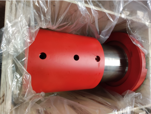
Drum Gear Coupling , www.timothyholding.com

Causes of Drum Gear Coupling Failures

1. System Design & Integration Issues

· Unbalanced Shaft System Compatibility:
Components in the drive train (e.g., diesel engines, gearboxes, shafts, and highly elastic couplings) must be mutually complementary in design and application. Sub-optimal integration or low manufacturing precision in any component may compromise the entire system.

Example: In marine applications, improper alignment between the main engine and propulsion system accelerates coupling wear.

2. Mechanical Overload & Misalignment

· Damper Subsidence in Prime Movers:
Subsidence of the main engine's vibration damper induces shaft misalignment, generating additional torsional loads.

Consequence: Excessive heat buildup in highly elastic couplings leads to thermal stress fractures.

· Insufficient Compensation Capacity:
Despite their angular displacement tolerance, drum gear couplings may fail under unanticipated combined loads (e.g., simultaneous axial, radial, and angular stresses)
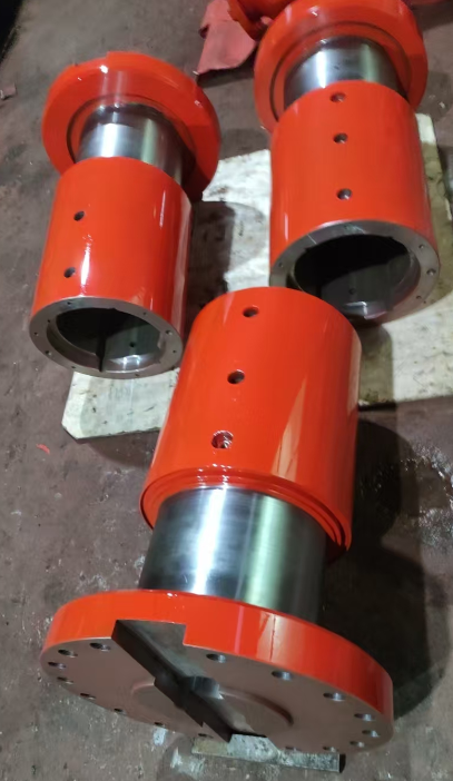
sleeve.pngsleeves.png.

3. Operational & Maintenance Factors

· Improper Usage:

Overloading beyond rated torque.

Frequent starts/stops or reverse operations in non-design conditions.

· Environmental Neglect:

Contamination (dust, moisture) entering unsealed lubrication cavities.

Failure to replace degraded lubricant, accelerating tooth surface wear.

4. Industry-Specific Challenges

· Broad Application Scope:
Widely used in heavy industries (metallurgy, mining, etc.), couplings face diverse operational stresses.

Risk: Misapplication in high-speed or ultra-precision scenarios beyond their design limits.

Key Takeaway:
Drum gear coupling failures often stem from systematic design flawsmechanical over-stress, or operational oversights. Regular alignment checks, load monitoring, and adherence to lubrication protocols are critical for longevity.


https://www.timothyholding.com/Causes-of-Drum-Gear-Coupling-Failures.html


Monday, June 9, 2025

Application and Considerations for Couplings in Rolling Mills


Application and Considerations for Couplings in Rolling Mills

文章附图

Application and Considerations for Couplings in Rolling Mills

1. Application of Couplings in Rolling Mills

Couplings are critical transmissioncomponents in rolling mills, connecting the motor, reducer, and work rolls totransmit torque and accommodate misalignment. The most commonly used typesinclude:

  • Gear Couplings: Widely     adopted due to their high torque capacity (standardized for <1000 kN·m     in China) and ability to handle slight angular/radial deviations.

  • Elastic Sleeve Pin Couplings: Used in some mills for their compact size and heavy-load     capability, suitable for low-speed, high-torque applications. However,     they are being phased out and should be avoided in new designs.

    sleeves.png

2. Key Considerations

  • Axial Load Resistance: Gear     couplings in rolling mills often endure heavy axial loads, which may shear     the sealing end cover screws, damage seals (causing oil leaks), and     accelerate gear wear. Solution: Increase screw diameter in     heavy-duty designs.

  • Precision & Balancing: For high-speed applications (e.g., roll shafts), couplings must be     dynamically balanced to minimize vibration.

  • Obsolescence Risk: Avoid     outdated designs like elastic sleeve pin couplings unless necessary for     legacy systems.

3. System Integration

Rolling mills consist of a prime mover(motor), transmission (couplings, gearboxes), and actuators (rolls). Propercoupling selection ensures efficient power transfer, reduces downtime, andextends equipment life.

Note: Regular maintenance (e.g., lubrication, sealinspection) is essential to prevent failures in harsh rolling mill conditions.


Translation Rationale:

  • Structure: Organized     into clear sections for technical readability.

  • Terminology: Uses     industry-standard terms (e.g., "dynamic balancing,"     "angular/radial deviations").

  • Conciseness: Combines     related ideas (e.g., axial load effects + solutions) for efficiency.

  • Warnings: Explicitly     flags phased-out components to align with the original text’s intent.

https://www.timothyholding.com/Application-of-Couplings-in-Rolling-Mills.html