Heavy-duty Vehicle Drive Shaft
Introduction
The Drive Shaft is a circular component that connects or assembles various parts, while being capable of moving or rotating. It is generally made of lightweight alloy steel tubes with excellent torsional resistance. For front-engine, rear-wheel-drive vehicles, it is the shaft that transmits the rotation of the transmission to the final drive. It can consist of multiple sections connected by universal joints. As a high-speed rotating body with minimal support, its dynamic balance is crucial. Typically, drive shafts undergo dynamic balance testing before leaving the factory and are adjusted on a balancing machine.
Function
The drive shaft is a key component for transmitting power in a vehicle's drive train. Its function, together with the gearbox and drive axle, is to transfer power from the engine to the wheels, enabling the vehicle to generate driving force.
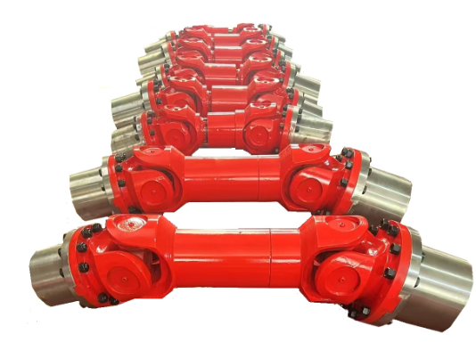
Applications
Special vehicle drive shafts are mainly used in models such as oil tankers, refueling trucks, sprinkler trucks, sewage suction trucks, fecal suction trucks, fire trucks, high-pressure cleaning trucks, road wreckers, aerial work platforms, and garbage trucks.
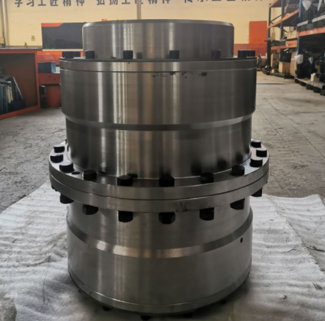
Structure
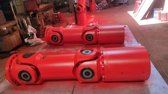
Universal Joint
The universal joint is a critical component of a vehicle's drive shaft. A vehicle is a moving object. In rear-wheel-drive vehicles, the engine, clutch, and transmission are mounted as a single unit on the frame, while the drive axle is connected to the frame via elastic suspension. There is a distance between these two assemblies, which requires a connection. During vehicle operation, uneven road surfaces cause jolting.
 |
| Heavy-duty Vehicle Drive Shaft,www.timothyholding.com |
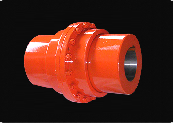
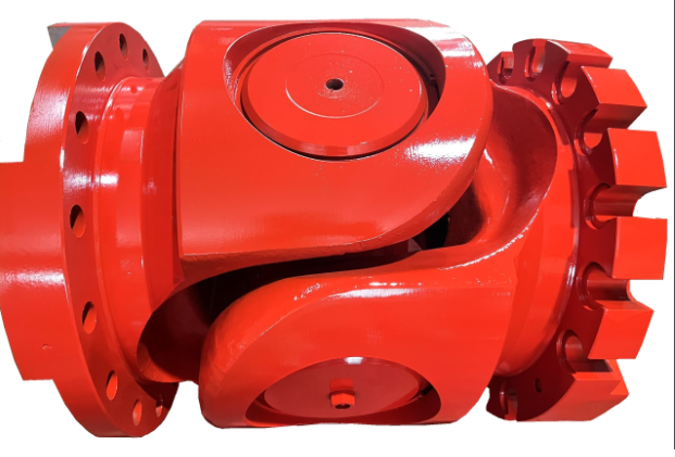
1. Function:
A typical universal joint is composed of a cross shaft, cross bearings, and a flange yoke. It is a key component of the vehicle's drive shaft. In front-engine, rear-wheel-drive vehicles, the universal joint drive shaft is installed between the transmission output shaft and the drive axle final drive input shaft. In front-engine, front-wheel-drive vehicles, the drive shaft is omitted, and universal joints are installed between the front axle half-shafts (which are responsible for both driving and steering) and the wheels. During vehicle operation, uneven road surfaces cause jolting, load changes, or differences in the installation positions of the two assemblies—all of which can alter the angle and distance between the transmission output shaft and the drive axle final drive input shaft. Therefore, a device that "adapts to changes" is needed to solve this problem, leading to the development of the universal joint.
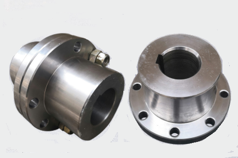
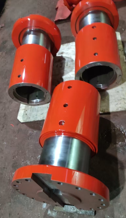
2. Transmission Characteristics:
This type of drive shaft adds a tubular sealing protective sleeve outside the flange spline shaft. Two polyurethane rubber oil seals are installed at the end of this protective sleeve, creating a fully sealed space inside the telescopic sleeve. This prevents the telescopic spline shaft from being eroded by external sand and dust, providing both dustproof and rustproof protection. Therefore, during assembly, applying lubricating grease once between the spline shaft and the sleeve fully meets the service requirements. There is no need to install an oil nipple for lubrication, reducing maintenance tasks.
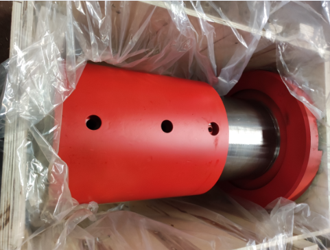
Shaft Bushing
Shaft bushings are designed to reduce friction and wear when the shaft moves. Their basic purpose is similar to that of bearings, and they are relatively cheaper. However, they have higher frictional resistance, so they are only used in some components. Most shaft bushings are made of copper, but plastic ones are also available. Shaft bushings are mostly placed between the shaft and the supporting structure, fitting tightly to the supporting structure—only the shaft can rotate on the bushing. When assembling the shaft and shaft bushing, lubricant is added between them to reduce friction during rotation.
| Heavy-duty Vehicle Drive Shaft,www.timothyholding.com |
Contact Name:August
Mobile Phone:+86-13758897904
Address:55# Jinshi Road ,Lecheng Industrial Park,Yueqing City,Zhejiang provice,China

 .
.