China Manufactuer of Cardan Shaft Universal Joint
 |
Cardan Shaft Universal Joint,www.timothyholding.com |
China Manufactuer of Cardan Shaft Universal Joint
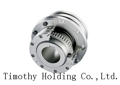
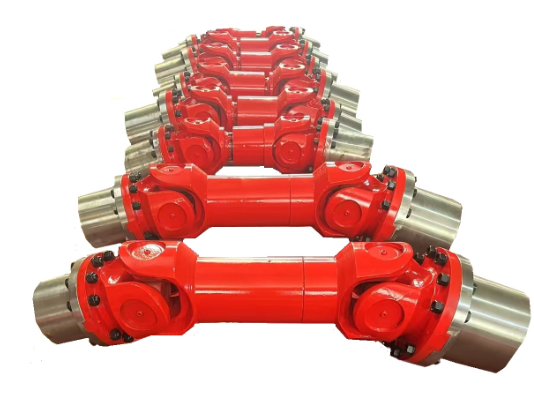
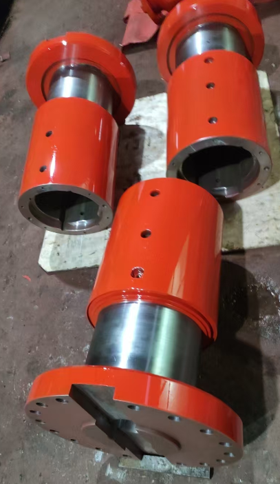
Performance Characteristics of Cardan Coupling
Cardan coupling is widely used in various industrial fields due to its excellent performance and characteristics. The following are the major performance characteristics of Cardan coupling:
High torque capacity
High misalignment tolerance
Smooth and vibration-free operation
Low maintenance requirements
High reliability and long service life
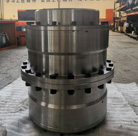
Types and Characteristics of Cardan Coupling
Cardan coupling can be divided into various types based on different classifications. The following are some common types and their characteristics:
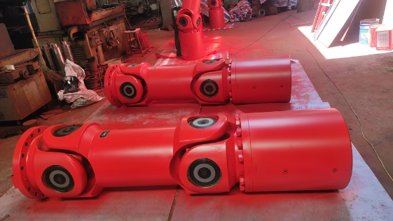
Single joint Cardan coupling: Simple structure, suitable for small angle misalignment
Double joint Cardan coupling: Complex structure, suitable for large angle misalignment
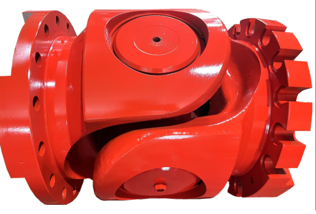
Flange Cardan coupling: High torsional stiffness, suitable for high-precision equipment
Slip Cardan coupling: High misalignment tolerance, suitable for complex working conditions.
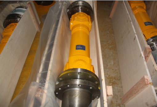
Advantages of Different Materials for Cardan Coupling
The material of Cardan coupling is an important factor that affects its performance and service life. The following are the advantages of Cardan coupling made of different materials:
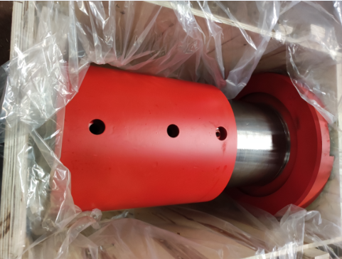
Steel Cardan coupling: High strength and durability, suitable for heavy-duty equipment
Aluminum Cardan coupling: Lightweight and corrosion-resistant, suitable for high-speed equipment
Stainless steel Cardan coupling: High corrosion resistance and hygiene, suitable for food and medical equipment
Titanium Cardan coupling: High temperature resistance and corrosion resistance, suitable for aerospace and military equipment
Contact Name:August
Mobile Phone:+86-13758897904
Address:55# Jinshi Road ,Lecheng Industrial Park,Yueqing City,Zhejiang provice,China

 .
.